Making a splash: It was a relatively simple invention yet it revolutionised long-distance train travel for more than a century.
Consultant Editor Nick Pigott dips into the subject of water troughs.
IT’S a hot summer’s day in the steam era and you are relaxing in a Pullman car speeding along the East Coast Main Line. After a while, a member of the catering crew leans across your table and gently slides the window shut. Apologising for disturbing you, he then does the same on the other side of the coach.
From the history of steam through to 21st century rail transport news, we have titles that cater for all rail enthusiasts. Covering diesels, modelling, steam and modern railways, check out our range of magazines and fantastic subscription offers.
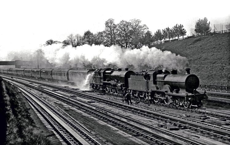
A couple of minutes later, your view of the passing scenery vanishes as the train appears to plunge into the mother of all rainstorms. Torrents of water lash against the windows and a passenger sitting a couple of seats behind you cries out as a few stray drops spatter her expensive new dress.
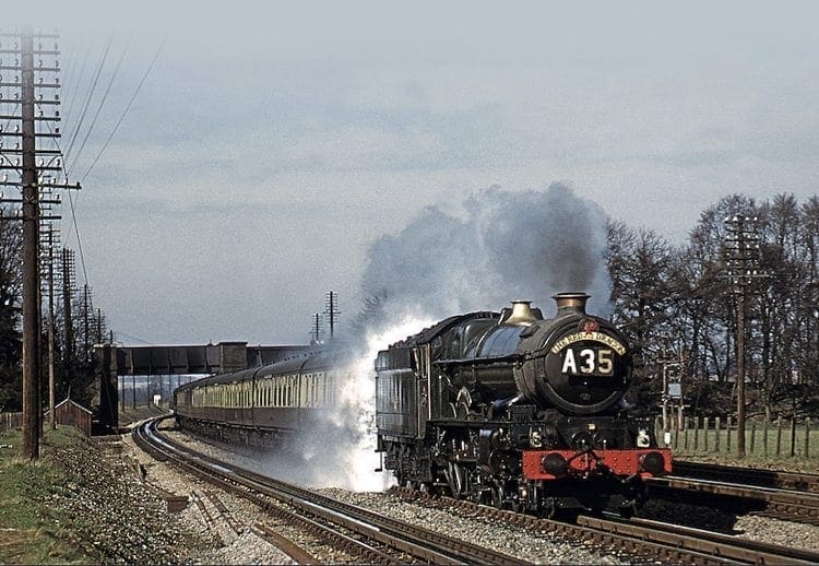
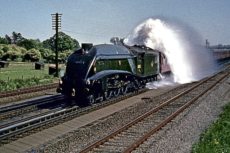
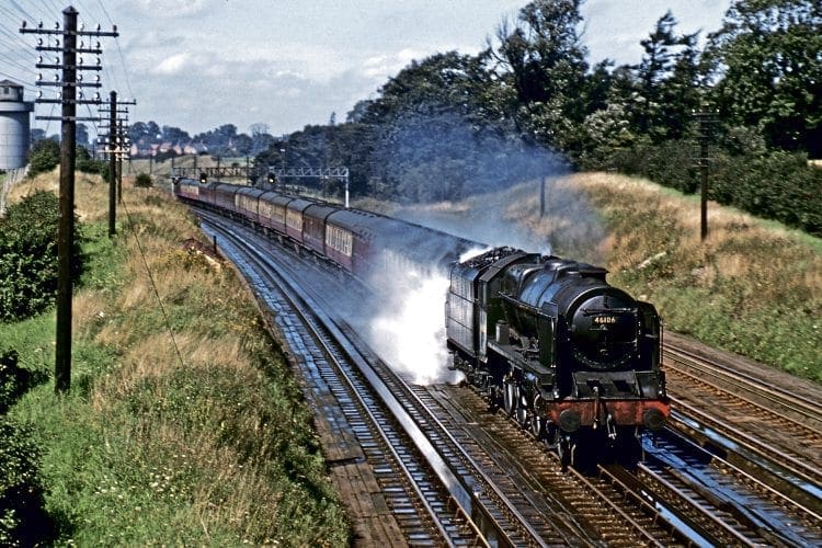
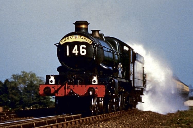
Out on the lineside, however, a lone photographer is clenching his fists in delight. He has captured that most spectacular of images – a tender overflow on a set of water troughs.
Such dramatic incidents took place whenever a fireman’s misjudgement or a mechanical fault prevented a water scoop from being withdrawn at the optimum moment. Not all passengers had the benefit of a steward or a conscientious guard to save them from a soaking, of course, and for the vast majority it was a case of finding out the hard way and learning from experience.
Few would have spared a thought for the driver and fireman, assuming their position ahead of the tender would keep them dry. Not always… a major tender overflow on a big engine at speed could sometimes cause chaos on the footplate as gallons of water cascaded over the coal, often bringing a pile of it down into the cab.
It was not unknown for crews to find themselves with a clear-up on their hands as they endeavoured to keep the train on schedule.
Troughs were very much a British phenomenon and there were more than 140 of them altogether, sited at some 60 different locations. In contrast, only two other nations – France and the USA – adopted them and only in a limited way, which is curious when it is considered how successful they were and how they revolutionised long-distance travel by enabling expresses to run non-stop for hundreds of miles.
They were a product of the extremely innovative mind of John Ramsbottom, locomotive superintendent of the London & North Western Railway, who was also responsible for the invention of the split piston ring, the sight-feed lubricator, the ‘Velocimeter’ speed recorder, and the safety valve that bears his name.
Innovative mind
At the end of the 1850s, the LNWR was under pressure from the Post Office and other customers to accelerate the ‘Irish Mail’ services by running the 84¾ miles between Chester and Holyhead in a little over two hours.
As a fleet of significantly faster engines was not really an option in those pioneering days, the only obvious solution was to increase the water capacity of the locos’ tenders. Under normal circumstances, the company’s largest 2,000-gallon tenders would just about suffice, but stormy weather was often experienced along the exposed North Wales coast and in such conditions consumption could rise by as much as 25 per cent. An alternative had to be found.
Ramsbottom realised that the only other way to meet the time challenge was to cut out the midway water stop and he thus came up with a novel ‘drink-and-drive’ solution for replenishing the supply.
His idea was based on the premise that a train’s impetus should be able to create sufficient pressure to force water upwards into the tender tank.
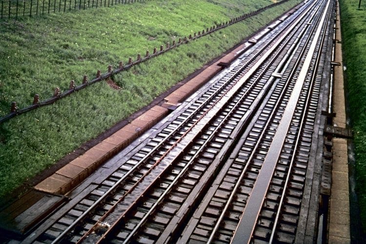
He arranged for long cast-iron troughs to be laid experimentally between the rails on the North Wales Coast Line at Mochdre, near Llandudno Junction, and fitted selected tenders with riser pipes and metal scoops.
He specified that the depth of water in the pans should be five inches but that only the top two should be skimmed, thus leaving three inches to allow for faulty mechanism, human error or foreign objects such as loco ash or stray ballast stones.
A ball-valve in a large trackside tank regulated the water at a constant level.
Optimum speed
In the trials, Ramsbottom’s prediction that a train speed of 15mph would lift the water 7ft 6in up the pipe and that it would stay at that level and not flow into the tender proved to be spot-on.
At higher speeds and with much trial and error, he found that 1,150 gallons could be forced into the tender at between 40 and 50mph. Anything slower – or faster! – was less efficient, the latter explained by greater spillage and the shorter time the scoop was in the water.
Having ascertained the optimum speed, the LNWR loco chief had to find a way of ensuring that his drivers (who up to that point had been estimating their speeds by a combination of sound, sight and experience) could be sure of running over the whole length of the pans at a constant rate.
He therefore introduced his ‘Velocimeter’, an early form of speedometer, consisting of an oil-filled glass tube linked by a cord to the engine’s rear axle. As the axle and tube span faster, the surface of the oil became more concave, allowing the driver to read off the speed on a vertical scale alongside the tube.
In this regard, his invention was way ahead of its time… several decades ahead in the case of many non-passenger engines.
The troughs were brought into use on June 23, 1860, and were so successful that the LNW laid sets on the West Coast Main Line to enable non-stop running over the 158 miles from London Euston to Crewe and the 141 miles onward to Carlisle.
A full set of the locations, along with those of other railway companies, can be seen in the table on page 23. It will be noted that in November 1871, the Mochdre troughs were lifted and moved to Aber, 11 miles further west.

Enabling tenders to be topped up en route had benefits other than the gaining of extra custom in a competitive market, for the system greatly reduced the dead-weight a locomotive had to lug behind it.
Even the 3,000 gallons of water carried by a modestly sized tender could weigh about 14 tons and on a through journey from London to Scotland, a loco could get through 70 tons’ worth, so further increases in tender capacity at that time would have had serious effects on efficiency.
A second important advantage centred around the fact that it wasn’t only the time spent taking water at stations that had to be factored into timetable planning but the precious minutes wasted decelerating for the stops and then slowly getting underway again.
Reducing the numbers of unnecessary halts not only shortened journey times but enabled routes to accommodate more trains.
Despite those benefits and the excellent national publicity the glamorous non-stop running generated for the LNWR, it took other companies until the latter years of the 19th century to follow suit, the Lancashire & Yorkshire being next to take the plunge when it embarked upon a major programme of installation across its network in 1885.
One reason for the delay had been the awarding of a patent to Mr Ramsbottom, but of more concern were high track maintenance costs due to a permanently wet permanent way, plus the fact that surprisingly long journeys were already being made by other railways without the need for troughs.
The Midland, for example, was managing as early as the 1880s to run non-stop between London and Leicester – a journey of just under 100 miles – and the Great Eastern had shown with a test train that it was possible to get from London to North Norfolk without stopping.
Rivalry
Given such marathons, it might be wondered how troughs ever became popular, yet both the Midland and Great Eastern eventually realised that it made more sense in terms of regular service trains to install them… and began doing so from the late-1890s.
Also slow off the mark were the Great Northern and North Eastern railways, which was rather surprising given their long rivalry with the LNWR for the lucrative Anglo-Scottish traffic and their highly competitive participation in the 1888 and 1895 ‘Races to the North’.
For those contests, they had undertaken frantic engine-changes at strategic stages of the route to provide trains with freshly watered steeds, while the LNWR had relied largely on its trough network to cover the near-300 miles of its West Coast route with just one stop.
The Caledonian Railway, which had laid no such devices at that stage despite being the North Western’s partner in the races, had to stop at least twice on the 240-mile run from Carlisle to Aberdeen, although on the last night of the 1895 contest, a skilful CR crew with a light train managed to cover the 150.8 miles between Carlisle and Perth using only the contents of a modest 3,572-gallon tender.
As the rival East Coast partners had normally had to make five stops on their 523-mile route, it was perhaps no surprise when the GNR decided in the early years of the 20th century to install four sets of facilities – at Langley, near Stevenage, Werrington, north of Peterborough, Muskham, near Newark, and Scrooby, south of Bawtry.
The sites chosen by the NER were the aptly named Wiske Moor, near Northallerton, and Lucker, south of Berwick, laid in 1898 and 1901 respectively.
Altogether, a dozen British railways adopted the trough system, the others being the Great Western, Great Central, Glasgow & South Western, Lancashire & Yorkshire (L&Y), the LNW/L&Y Joint and the GWR/LNW Joint. In America (where they were known as ‘track pans’), they were installed by the Pennsylvania and New York Central railroads, while in France, they were to be found only on the Etat.
The main exceptions in England were the railways of the South-East, where distances were relatively short compared with those north of the Thames.
Only the London & South Western Railway had a route long enough to justify the expense of installation, but its managers, and those of its successor companies, preferred large tenders (nicknamed ‘water carts’) and engine-changes at Salisbury.
At the other extreme, one of the greatest users of troughs was the Great Western, which began streamlining several of its routes by constructing ‘cut-off lines and laying sets of pans in the early part of the 20th century.
One of the latter, at Creech, east of Taunton, enabled the GW to claim the ‘longest non-stop run in the world’ in 1902 when it operated a remarkable 246½-mile Royal Train special between Kingswear and Paddington.
By then, wooden and cast iron troughs had given way to galvanised steel, which was more suited to regular rough usage and harsh conditions, and the maximum water depth on some railways had increased to eight inches with a consequently deeper skim.
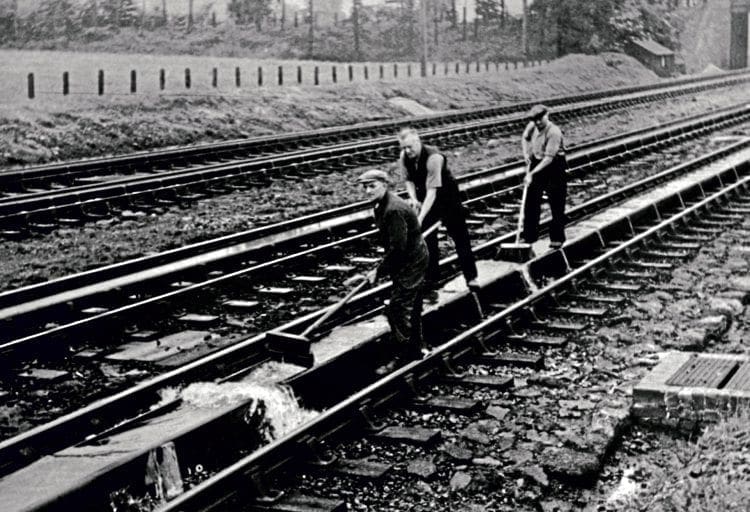
To ensure that the level of water relative to the position of its trough remained absolutely constant along its whole length, the ballast under the sleepers had to be regularly packed and monitored by track maintenance gangs.
Several locations with quadruple routes, Goring and Bushey for example, possessed pans on all four tracks, but most sites were double-track affairs. Widths of pans ranged from 15 to 18 inches and the distances between sets of troughs varied from 25 to 90 miles, although the average was 30 to 60.
The subject is far more complex than might first appear. For a start, selecting a location was not simply a matter of finding a level section of track. Several other factors had to be taken into consideration: The site had to feature dead-straight or very gently curved permanent way, could not be too close to stations, public crossings or turnouts, had to be the requisite distance from the previous set of troughs and, ideally, shouldn’t be on an embankment as constant soakings or burst pipes could weaken or wash away the earthworks.
Unusual sitings
The rail chairs and fittings were usually of a heavier design than normal and the sleepers were spaced slightly closer together than on standard permanent way to provide firm support for the pans and keep them from shifting.
Even the ballast stones were bigger and heavier, partly to prevent the road from being washed away by the constant spillage and partly to reduce the risk of small stones being thrown up into the pans and causing an obstruction.
Some railways preferred to use heavy lumps of furnace slag rather than granite. Finally, there had to be a ready supply of water nearby, preferably a river, canal, spring or bore-hole, although other sources were sometimes used.
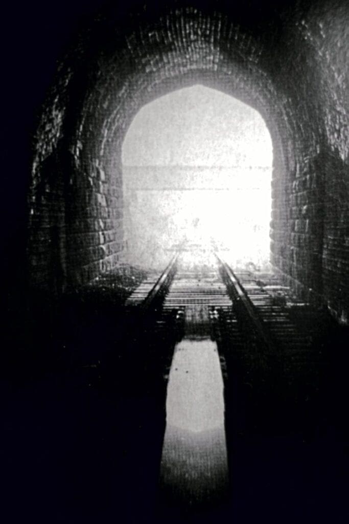
Those parameters led to some unusual sitings; the only suitably level place the LNWR could find on its cross-Pennine route for example, was inside the western end of Standedge tunnel.
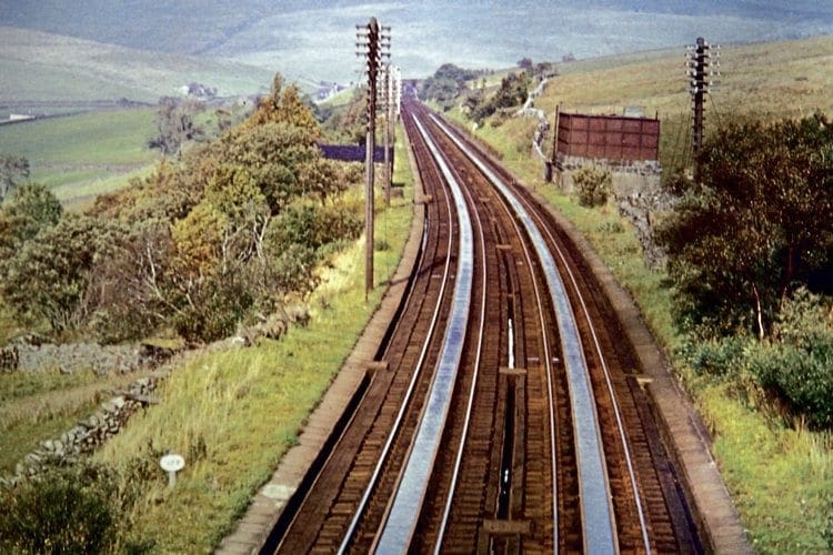
The Midland Railway installed a set at Garsdale, 1,100ft above sea level on the Settle & Carlisle line, and was able to boast ‘the highest water troughs in the world’.
In heavily industrialised areas, local water was not always of the desired quality, being contaminated with mud, lime, magnesia or run-off of hazardous liquids from chemical or manufacturing plants.
As it did not matter much to 10 miles or so where exactly the troughs were situated, it was often possible to choose a spot where a natural supply of good water could be had cheaply.
Design of the equipment was important too. End walls could not be fitted to retain the liquid because of the risk of a scoop smashing into them either on entry or exit, so the troughs were made to slope gently upwards for the final few yards at each end to contain the liquid and also allow the scoop to enter and leave in a gradual manner.
That was important because hitting the full depth of water too suddenly could damage the mechanism. The running rails too had to fall and rise accordingly.
For most of the trough’s length they were laid on a level slightly lower than the surface of the water, but to prevent the sloping ends of the pans protruding too high, a short incline was created in the track at the start and finish, so that trains ran downhill into the water on a gradient of approximately 1-in-350 and then up a similar incline at the other end.
Spillage was a big problem in the early years because, even without tender overflows, huge quantities of water were flung from the troughs in the normal course of operation.
Drains beneath the ballast and angled slabs at the side helped recover some of it, but a lot of otherwise usable water simply drained into the earth.
To begin with, the side walls of the pans were vertical, but as a result of this constant flooding – not only when trains ran through but during high winds when the water formed waves and lapped over the sides – the walls were redesigned to feature an inward-facing lip at the top.
Then, in the 1930s, LMS engineers rigged up a special tender in which a research technician was able, in cramped circumstances, to observe the action of water at speed.
From these tests, it was seen that the fluid was ‘piling up’ like a bow wave in front of the scoop and slopping over the sides. By fitting a small deflector plate about 16 inches ahead of the tender scoop, the water could instead be guided into its mouth.
That small modification was eventually adopted by the other railways and saved an astonishing 400 gallons for every train – a remarkable 20% saving overall. It also permitted trains to pass through the water at speeds of up to 75mph, an important consideration with the expresses of the ‘Big Four’ and BR eras.
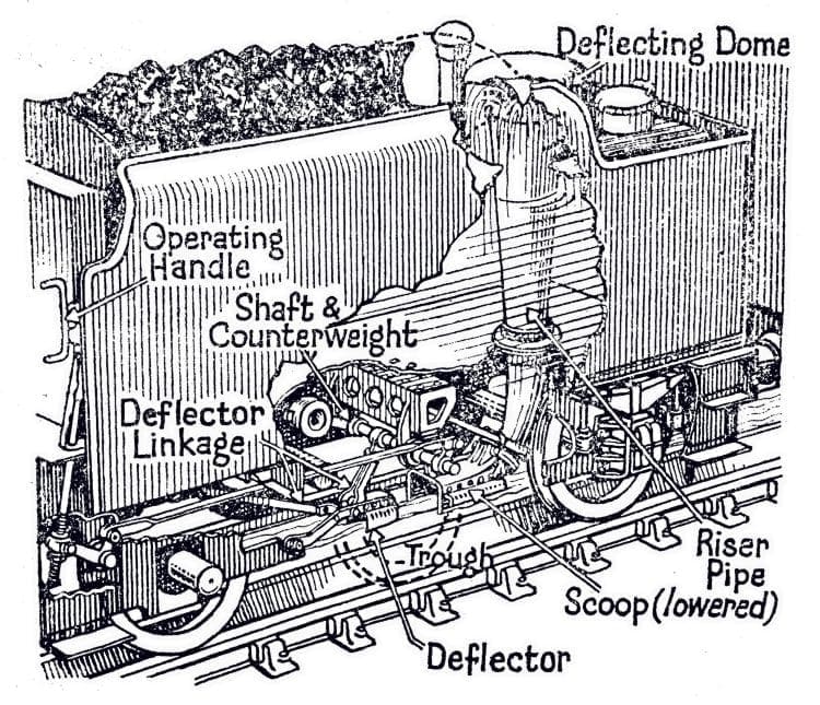
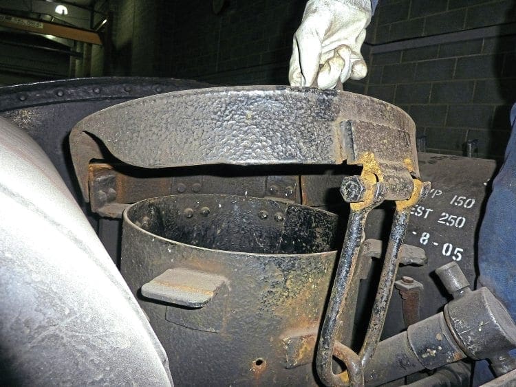
Other aspects of tender design were important too. The scoop-lowering mechanism featured a shaft and counterweight and the riser pipe, sometimes vertical and sometimes angled, led to a large mushroom-shaped deflecting dome which bore the force of the inrushing water and re-directed it downwards into the tender tank.
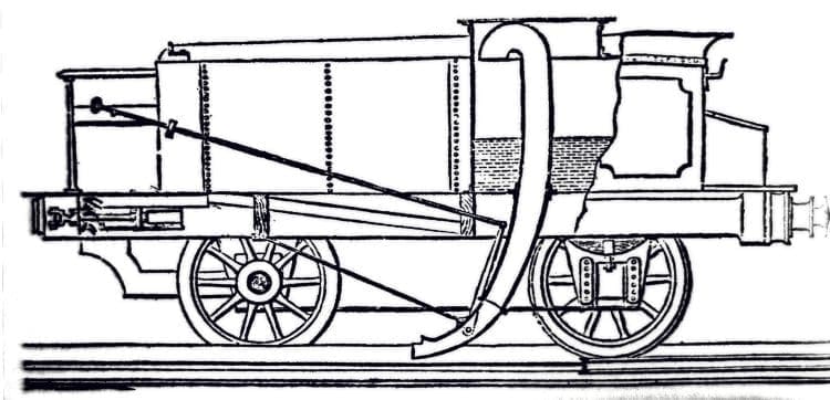
To prevent a build-up of air pressure inside the tank, two smaller ‘mushrooms’ (such as those readily visible on the rear of WD and larger LMS tenders) acted as air vents. At 60mph, tenders could gather 2,000 gallons or more in as little as 20 seconds.
Early forms of scoop were lowered and raised by rods but after numerous difficulties, designers began introducing ones operated by a screw-thread wound up and down by a wheel mounted on the cab end of the tender.
Apart from being easier to operate, the more accurate mechanism reduced the chances of scoops being lowered to the wrong depth. As locomotive development became more advanced, steam or compressed air was used to operate them on many engines, thereby increasing accuracy still further.
Mauling
In theory, the collecting of water was a simple affair. The fireman just lowered the scoop, watched the water level gauge and, when the tank was almost full, lifted it.
In practice, it wasn’t always that easy, and most fireman had at least one amusing or hair-raising tale to tell about scoops they couldn’t get out of the water in time, no matter how hard he (and often the driver too) grappled with it.
Author and former LNER footplateman Norman McKillop once described such an experience on an ex-Great Northern ‘D1’ class 4-4-0: “Those engines could certainly run at speed, but the mauling the poor driver and fireman received left them feeling as if they had just finished an hour or two with an all-in wrestler.
“The water scoop had a weird straight-pull lever and strong men blenched at the first experience they received of its inadequacy. Once it entered a full water trough, nothing human could induce it to come out until the very end of the trough was reached, and then it gave way suddenly to precipitate the unfortunate operator on his back amid cascading tons of water and coals descending into the cab!”
The first thing the crew of a scoop-fitted locomotive had to do each day was to ensure that the apparatus was in the raised position before the engine went off shed, as failure to make that simple check could result in the loco having to be taken out of service.
Once out on the main line, the problem was getting the timing of the ‘dip’ or ‘skim’ just right. Alongside the entrance of most troughs was a large white lineside board depicting a zig-zag black line showing the fireman where to drop the scoop, but on fast trains that was easier said than done, especially if the mechanism was stiff or obstinate.
Once the drop had been executed successfully, the next big challenge was to get the correct amount of water into the tender tank (which wasn’t necessarily completely empty, of course).
Even with the aid of gauges, judging the precise moment to remove the scoop wasn’t always an exact science and an overflow would then result.
In addition to the hazards already noted, there was another major danger to consider with overflows… the risk of poorly trimmed coal being knocked off the tender and either hitting the windows of passing trains or injuring track workers.
In one incident on the LMS, two streamlined trains hauled by ‘Princess Coronation’ class locomotives passed each other at a combined speed of around 100mph while taking water. The number of damaged windows and passenger complaints led to operational changes to try to reduce the chances of re-occurrence.
The Royal Family already benefited from such special treatment, for signalmen on all railways were under strict instructions not to allow any other service to be signalled into a trough section at the same time as the Royal Train was passing through it.
There is another consideration with regard to overflows and that concerns double-heading, for it was not unknown for coal and water to be knocked off the tender of the pilot engine and cause difficulties for the men on the train engine.
For that reason, crews of double-headed trains had to agree among themselves beforehand which loco was going to take water first, and for how long… for it was not efficient practice for both engines to have their scoops down simultaneously and it was therefore a matter of sharing what was in the trough if both engines were to get their required ‘drink’.
A set of whistle codes existed if crews ever needed to notify signalmen of problems with regard to water.
When it is considered that total water resistance under certain circumstances could almost equal drawbar pull and thus slow a train’s progress, it is perhaps not surprising that the top two or three inches only were skimmed.
Compensate
This resistance posed challenges to drivers. Those of express trains travelling in excess of 80 or 90mph had to reduce their speed on the approach to a trough section and then increase power slightly as they entered the water in order to compensate for the ‘dragging’ effect, which would otherwise have slowed the train further.
This was even more of a problem for the crews of loose-coupled goods trains, for if a driver misjudged the compensation, the couplings between the wagons could become slack.
A fair degree of skill thus had to be used, not only to accelerate the train slightly but to maintain a constant speed for the whole length of the pans in order to keep the couplings tight.
Failure to do so would see the engine surge forward as the scoop was raised, ‘snatching’ the couplings and possibly dividing the train or at the very least badly jolting the guard.
In the early years, troughs extended for about 400 yards, but lengths gradually increased to 560 or 600 yards and some extended for almost half-a-mile.
When full, a 560yd trough contained about 5,750 gallons and a single pass of a large locomotive at 45mph could remove about half of that, which meant that the cistern-style tank, balanced valve and large-bore pipework had to work hard to get almost 3,000 gallons into the pans before the next train was due, which on some busy days could be only four or five minutes later.
To ensure plenty of water was always on hand, an average-sized trackside tankhouse could store about 40,000 gallons and in areas of hard water, a large softening plant was usually positioned alongside to help prolong boiler life, for even water pure enough for household use can scale the inside of a boiler if it originates from chalk or limestone measures.
As little as a quarter of an inch of scale caused by hard water can result in a boiler whose evaporative ability is so inefficient that coal consumption is doubled! (Often to be seen alongside a softening plant would be an old tender, being utilised as a ‘sludge carrier’.)
Another problem was ice. With anything up to 100 trains a day passing some sets of main line troughs, there was little chance for this to form to any dangerous degree of thickness, but on less well-used routes or in the early hours of the morning, it could be a different story.
Keeping the ice broken was a hazardous job for the permanent way gangs, not only because of the risk of being hit by flying ice as trains passed but because of the constant risk of slipping on the timber sleepers and breaking limbs.
Consequently, some troughs were fitted with steam-heating pipes, but in many cases it was a case of emptying them on freezing nights and instructing engine crews not to use them. Inevitably some drivers forgot and there was at least one case of a loco running out of water and dropping a fusible plug.
Double-scoops
It wasn’t only tender engines that could use troughs. On the LNWR, L&Y and GWR in particular, several tank engines were fitted with specially designed double scoops that faced both ways.
When running bunker-first, this had the effect of throwing considerable quantities of cold water onto the hot firebox and ashpan area, creating huge clouds of steam in addition to the spray!
One tank loco, GWR 2-4-2T No. 11, became the subject of railwaymen’s yarns for decades afterwards when air displaced by incoming water could not escape quickly enough through the top vent… causing the tank sides to be split open by the air pressure! Larger vents had to be fitted to that and other tank engines to prevent a re-occurrence.
During the BR locomotive exchange trials of 1948, ‘Princess Coronation’ No. 46236 City of Bradford had to be coupled to an eight-wheeled ‘Austerity’ tender owing to the lack of troughs on the Southern Region.
On the other hand, Southern Pacifics had to borrow LMS tenders in order to use the troughs on other regions.
Trough facilities were expensive to maintain, generally requiring a pumping station, miles of plumbing and at least a couple of employees.
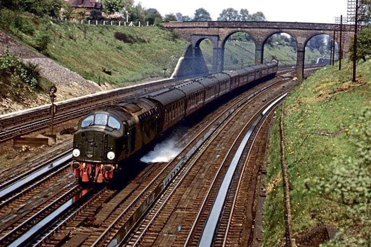
Most were dismantled during the demise of steam traction on BR in the 1960s (those at Aber going in 1967 after more than a century of use), but several remained in situ for a few years to enable the steam-heating boilers of scoop-fitted diesel locomotives, including ‘Deltics’ and Class 40s, to be topped up en route and thereby maintain non-stop schedules on long-distance services.
Sadly, no troughs remain and it is no longer possible for enthusiasts or members of the public to enjoy the harmless pastime of standing by a lineside fence just for the fun of it and getting a good soaking.
Anyone within 20ft of the track was likely to get a dousing as a ‘King’, ‘Duchess’ or ‘A4’ ploughed into the water at speed, although spectators of a more genteel nature could stand a little further back on a sunny day and enjoy the colourful sight of ‘rainbow-spray’.
Demonstration pan
Along with slip coaches, troughs are among the few significant features of the steam age the heritage world has not yet managed to replicate, but a movement that can build an LNER Pacific and reinstate a bridge over a four-track main line should have little problem with a short demonstration pan filled with rainwater or fed from a road tanker.
In the same way that crowds at Great Central galas line the trackside to watch mailbag collection trains, it might provide an additional spectacle should tourists of the 2020s ever begin to tire of the usual attractions. They would have to be warned to bring waterproofs though! ■
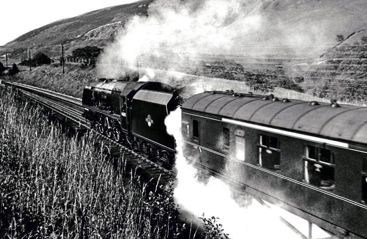
Getting lucky at Lucker
IN the days leading up to the preserved Flying Scotsman’s historic non-stop run from King’s Cross to Edinburgh on May 1, 1968, loco owner Alan Pegler became convinced that ‘LMS supporters’ within BR were determined to sabotage the daring attempt.
He must have thought he was right when it turned out that BR had ‘forgotten’ to raise the level of water at Scrooby, Wiske Moor and Lucker, meaning that the ‘A3’ gathered less than it should have done.
The real nerve-jangler occurred at Lucker, though. The signalman there had been told that a long whistle from the loco would mean insufficient water had been taken and that the train would have to stop at Berwick to use a road tanker Pegler had booked there as a precaution.
The signalman heard a long whistle and duly advised Berwick that a stop was to be made – but, unbeknown to him, a foolish photographer had chosen to lie on his stomach inches from the line and it was that which had caused the ‘A3’ driver to whistle!
As the footplate inspector had by then decided to risk continuing to Edinburgh with what was left in the tender tank, the crew had to shout out to the Berwick signaller to be allowed to run non-stop through the goods loop… and on to victory.
On the southbound non-stop run three days later, Pegler’s team took no chances and one of them obtained a set of keys to Scrooby troughs and held the ball-cock down with his hand.
By the time ‘Scotsman’ arrived, the water was overflowing!
The water troughs of Britain
London & North Western
Mochdre (east of Llandudno Jct), 508yds, 1860 *
Aber (between Llanfairfechan and Bangor), 1871 *
Prestatyn (between there and Rhyl), 510yds, 1885.
Flint (between there and Connah’s Quay), 560yds, 1895.
Bushey (south of Watford Jct), 503yards, 1860s.
Castlethorpe (north of Wolverton), 559yds, 1860s.
Newbold (north of Rugby), 554yds, 1860s.
Whitmore (between there and Madeley), 563yds, 1860s.
Moore (south of Warrington) 579yds, 1860s.
Brock (between there and Garstang), 561yds, 1860s.
Hest Bank (north of Lancaster), 562yds, 1860s.
Dillicar (a.k.a Tebay), south of Tebay, 553yds, 1861.
Holbrook Park (west of Rugby), 554yds, 1860s.
Hademore (between Tamworth and Lichfield), 642yds, 1860s.
Diggle (inside west end of Eccles), 503/554yds, 1878.
Eccles (east of Patricroft), 1870s.
Halebank (between Widnes and Speke Jct), 1870s.
Chester (between Chester General and Waverton), 557yds
* These troughs were moved from Mochdre to Aber in 1871.
Lancashire & Yorkshire
Horbury Jct (west of Wakefield Kirkgate), 1885.
Hoscar (between there and Burscough West Jct), 1885.
Kirkby (between there and Fazackerley Jct), 1885.
Lostock Jct (west of Bolton), 1890.
Rufford (between there and Burscough North Jct), 1885.
Smithy Bridge (north of Rochdale), 1885.
Sowerby Bridge (between there and Luddendenfoot), 1885.
Walkden (between Atherton and Swinton), 1885.
Whitley Bridge (between Knottingley and Hensall Jct), c1890.
Preston & Wyre (LNW/L&Y Joint)
Lea Road (between Preston and Kirkham & Wesham),
561yds, 1885.
Great Western
Aldermaston (between Reading and Newbury), 620yds, 1906.
Aynho (a.k.a. King’s Sutton), between Aynho Jct and King’s Sutton, 560yds, c1895.
Charlbury (between Oxford and Kingham), 560yds, c1895.
Creech (between Taunton and Cogload Jct), 560yds, 1902.
Denham (a.k.a. Ickenham) (between Ruislip and Denham E Jct), 560yds, 1905.
Exminster (between Exeter and Starcross), 560yds, 1904.
Fairwood (west of Westbury), 553yds Up line, 495yds Down line, 1906.
Ferryside (between there and Carmarthen Jct), 620yds, 1906.
Goring (a.k.a. Basildon), between Reading and Didcot,
620yds, 1895.
Keynsham (a.k.a. Fox’s Wood), between Keynsham and
St Anne’s Pk. 620yds. 1895.
Rowington (a.k.a. Kingswood, also Lapworth), north of Hatton. 440yds/560yds. 1895.
Sodbury (a.k.a. Chipping Sodbury), between there and Sodbury tunnel, 524yds, 1903.
Undy (a.k.a.Magor) (between Severn Tunnel Jct and Newport) 560yds (fast lines only) 1906
(H Holcroft, in the book An Outline of GW Locomotive Practice, stated that a set of troughs was laid at Lostwithiel, Cornwall, circa 1908, but they are not mentioned in the GWR records of 1936).
Shrewsbury & Hereford (GW/LNW Joint)
Ludlow (a.k.a. Bromfield), between Clee Hill Jct and Bromfield. 613yds, c1900.
Great Northern
Langley (south of Stevenage), 694yds, 1918.
Werrington (north of Peterborough), 638yds, 1900.
Muskham (north of Newark), 704yds, 1900.
Scrooby (south of Bawtry), 704yds, 1902.
North Eastern
Wiske Moor (a.k.a. Danby Wiske), north of Northallerton, 613yds, 1901.
Lucker (between Alnmouth and Berwick), 613yds, 1898.
Midland
Oakley (between Bedford and Sharnbrook), 557yds, 1903/4.
Hathern (a.k.a. Loughborough), between Loughborough Midland and Kegworth, 557yds, 1904/5.
Melton (a.k.a. Brentingby), east of Melton Mowbray,
557yds, 1905.
Haselour (north of Tamworth High Level), 1909.
Hawes (a.k.a. Garsdale), south of Hawes Jct, 554yds, 1907.
Great Central
Charwelton (between Woodford Halse and Rugby Central), 1903.
Eckington (a.k.a. Killamarsh), between Staveley and Killamarsh, 1904.
Great Eastern
Halifax Jct (south of Ipswich), 1897
Tivetshall (north of Diss), 1896/7.
Caledonian (under LMS ownership)
Floriston (between Carlisle and Gretna) 560yds, 1927.
Strawfrank (a.k.a. Pettinain), south of Carstairs, 557yds, 1927.
Glasgow & South Western (under LMS ownership)
New Cumnock (between there and Kirkconnel) 564yds, 1927.
A tragic fatality
ON January 16, 1958, Whitmore water troughs were the indirect cause of a schoolboy’s death. He and a pal had stowed away on the rear of the tender of the ‘Shamrock’ express from Euston to Liverpool and weren’t discovered by the fireman until the train was 150 miles from London, by which time one of them was lying unconscious among the coals.
The train was halted at Madeley signalbox and the boys taken into the cabin to await an ambulance, but the injured lad died before he could reach hospital.
It transpired that when the train ran over the troughs, overflowing water soaked the boys and in shock they stood up – an action that caused one of them to receive fatal head injuries from an overhead obstruction.
The Railway Magazine Archive
Access to The Railway Magazine digital archive online, on your computer, tablet, and smartphone. The archive is now complete – with 123 years of back issues available, that’s 140,000 pages of your favourite rail news magazine.
The archive is available to subscribers of The Railway Magazine, and can be purchased as an add-on for just £24 per year. Existing subscribers should click the Add Archive button above, or call 01507 529529 – you will need your subscription details to hand. Follow @railwayarchive on Twitter.