First published in the January 1956 issue of The Railway Magazine, this article documents the reconstruction of Potters Bar Station and the quadruplication of the East Coast main line through the site. Reproduced here as a historical retrospective, it offers a contemporary account of the engineering, architectural design and passenger facilities introduced as part of British Railways’ mid-1950s modernisation programme.
Reconstruction works and track alterations
RECENTLY completed, at a cost of more than £500,000, the reconstruction of Potters Bar Station (12½ miles from Kings Cross) is part of the major scheme for removing the serious two-track bottleneck, which extended southwards through the tunnels to Greenwood Signalbox, near New Barnet. There are now four tracks from the north end of Potters Bar Tunnel, through the station, to the previously-completed four-track section on the north side.
New station design and passenger facilities
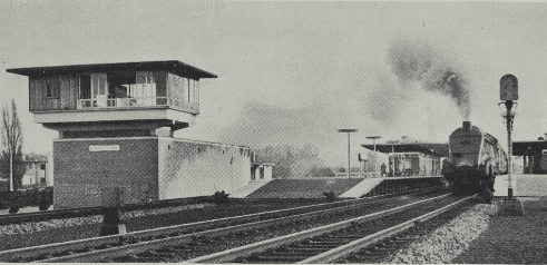
The new station is of striking design, and consists of two island platforms. Maximum comfort has been provided for passengers. It is the first main-line station reconstruction to be completed by the Eastern Region since announcement of the modernisation plan for British Railways. The work has taken three years to complete.
From the history of steam through to 21st century rail transport news, we have titles that cater for all rail enthusiasts. Covering diesels, modelling, steam and modern railways, check out our range of magazines and fantastic subscription offers.
Approaches, parking and site layout
The approaches to the main station building have been completely redesigned, and embody provision for car parking and lock-up garages. For the most part, the site was undeveloped before building began, but the site of the main station building and forecourt was occupied by a coal stacking ground. The buildings are all of single-storey construction, with the exception of the signalbox, which has exceptional appearance at first floor level, and is the north end and highest point of the site, to command the best view.
Ticket hall and booking arrangements
The ticket hall is entered through swing doors, and passenger bookings and enquiries are dealt with in a combined office, which also handles parcels traffic and left luggage. The main station building is sited with the booking hall on the axis of the subway to afford direct entrance to the platforms for season ticket holders from either the paved pedestrian way or from motor vehicles via the covered main entrance. The ticket office windows are placed so that queues can form without impeding the main flow of ticket-holding passengers. Ticket control is in the subway, between the ramps to the up and down platforms, to enable one ticket collector to control both platforms at off-peak hours.
Platform access and waiting areas
From the ticket hall, passengers proceed by the subway and through to the platforms by ramps. The waiting rooms are centrally heated and tastefully finished with carefully selected tones of easily washable emulsion paint. The seating in the waiting rooms has been specially designed, and tables are of tubular steel, with plastic tops. Lavatories are completely modern in design, and throughout the station extensive use has been made of wall tiles. Here again, the emphasis is on ease of cleaning, and the whole station has been designed to reduce maintenance to an absolute minimum. The platform buildings are sited as near the centre of each platform as possible, and greater public accommodation is provided on the up platform, which will be used by travellers to London.
Platform roofs and structural design
Each platform roof consists of prestressed cantilever slabs connected with two longitudinal cantilever beams forming an inverted T. The two beams in each unit are supported by four columns. The slabs are approximately 4 in. thick, and contain pre-stressing cables arranged transverse to the main direction of the platform. The beams are of balanced design; that is to say, under normal dead weight, the loads outside and inside the columns are balanced. Pre-stressing cables are provided at the upper side of the beams with the result that the surface roof is concave. The upper surface under dead and maximum loading, this curvature would be somewhat reduced. The pillars supporting the cold cathode light fitting for platform lighting are also of concrete.
Signalbox and control facilities
At the north end of the up platform, the new signalbox which controls the new colour-light signalling. From the elevated signal room, signalmen have a clear view of the tracks by day and by night, and all amenities are provided for them in the box. Below the signal room are housed the banks of electrical relays. Detailed reference to the new signalling was made in the November 1955 issue.
Goods office reorganisation
The goods work of the station also has been reorganised. The goods office is on the up side, and is so sited that the clerks have a view across the forecourt. The public space is entered directly from the pavement, and the wages staff accommodation forms a wing with the Yard Foreman’s office on the north end commanding a view of the goods yard. A bench of modern design has been provided for the exchange of goods between railway wagons and road vehicles.
Bridge reconstruction and road widening
One of the major features of the quadruplication of the line through the station was the reconstruction of the bridge over Darkes Lane at the south end. This bridge now carries four tracks, and the road beneath has been widened and lowered by the Middlesex County Council, so that it can be used by double-deck buses. It has two single and two double-track spans, all of 60 ft., and the headway over the road is 16 ft., compared with 11 ft. with the old bridge.
Engineering works and foundations
The spans are constructed of fabricated steel plates, with stiffeners on the inside faces only, leaving an unbroken face externally. The decks are carried on cross bearers seated on special brackets fixed to the bottom of the girder webs, concrete filled on mat reinforcement, waterproofed and tiled. The girders are mounted on grillages fixed to the tops of abutments, the free end being mounted on phosphor bronze blocks fixed to the grillages and girder ends. The whole is carried on abutments 10 ft. thick of concrete faced with blue engineering brick.
Completion and operational considerations
The major civil engineering works generally completed with the construction of the middle double-track span of the new bridge, and the restoration of the main lines in March of last year. Their execution in programmed stages, with the necessity to maintain traffic at all times, and to minimise inconvenience to passengers, was a formidable task, especially in view of extremely bad weather, and the difficulty of operating plant over a waterlogged site containing clay.
First published in The Railway Magazine, January 1956. To access the full archive, subscribe to the magazine here https://www.classicmagazines.co.uk/the-railway-magazine