An extract from the April 1938 issue of The Railway Magazine describing the Kofler automatic train stop system. The article outlines its design, operation and trials on European railways.
Introduction and Trials
The Kofler Automatic Train Stop
IT has recently been announced that the automatic train stop invented by the Austrian engineer, Herr George Kofler, is to be installed for trial on the Tluscz-Ostrolenka line in Poland, and the Resnik-Rypina section of the Jugoslavian Railways. These trials follow others already made on the Isar Valley and Cologne-Bonn electric lines in Germany, and the electrified section of the North Milan Railway in Italy. The apparatus was originally purely mechanical, but the inventor has added a supplementary electric warning and checking device incorporating luminous cab-signal indications, which enables so-called “vigilance” action to be used if desired. Its use is not, however, essential.
From the history of steam through to 21st century rail transport news, we have titles that cater for all rail enthusiasts. Covering diesels, modelling, steam and modern railways, check out our range of magazines and fantastic subscription offers.
Equipment and Function
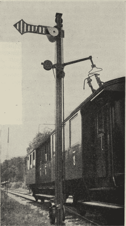
The equipment consists of a special form of trip arm mounted on a short post at the side of the track and securely fixed in relation thereto, moving normally in agreement with the fixed semaphore or other type of signal. This trip arm, when the signal is in the “on” position, comes into contact with specially shaped spring-loaded bow levers on top of the locomotive or vehicle concerned, so as to move them downwards and act on the warning whistle, brake apparatus or both, as desired. Distant and stop signals are actuated by different bows, the relative trip arms being placed to suit, and of course there is a difference in the action on the train. The absolute stop effect cannot be cancelled by the driver until the train is at rest, whereas the distant signal brake application can be cancelled under proper conditions. The electric warning device, which includes lamps and a hooter, is arranged to compel the driver to make a movement with his brake handle when a trip arm acts on the train, or to produce the necessary action after a short time interval should he neglect to do so.
Mechanical Operation and Safety
The trip arm is not rigidly connected to the signal-operating rodding, but through a latch mechanism, for the purpose of releasing it from the operative position and allowing it to move clear of the gauge limit as soon as its work has been accomplished; this reduces to a minimum any risk of the trip arm being damaged, say by some load that is accidentally foul of the gauge. For this purpose the train carries a fixed bow a short distance in rear of the movable one, and when the striking end of the trip arm comes against it the arm is rotated on its own axis far enough to release a pawl and allow a spring to move it upwards well clear of the gauge. As soon as the signal is moved to “off” the pawl mechanism re-engages so that the arm once more moves into the operative position when the signal is put to “danger”. The apparatus is simple and strongly constructed, and it is claimed that the design reduces shock to a minimum, enabling it to be used under high speed conditions without risk of damage or failure.
This article is available to subscribers of The Railway Magazine, along with every article from issues dating back to the 1800s! To subscribe, visit https://www.classicmagazines.co.uk/the-railway-magazine