An archive article from the June 1959 issue of The Railway Magazine describing the new route-relay interlocking signalbox at Newcastle Central Station, detailing its layout, signalling equipment, telecommunications systems, relay installations, and electrical infrastructure.
The North Eastern Region of British Railways has brought into operation a new route-relay interlocking signalbox above the platforms in the centre of Newcastle Central Station. The signalbox controls some ten miles of line, including Manors Station, and the High Level and King Edward Bridges, and covering the western main line as far as the entrance to the Forth Goods Yard, where the existing signalbox remains in service. The new box, of 641 route switches, with provision for extension, replaces four electro-pneumatic power boxes of individual lever type.
The intensity of traffic passing through this area is illustrated by the fact that on most Saturdays in summer over 340 suburban electric trains, 420 steam and diesel main-line and suburban trains, and some 80 freight trains use the lines controlled from the new signalbox.
From the history of steam through to 21st century rail transport news, we have titles that cater for all rail enthusiasts. Covering diesels, modelling, steam and modern railways, check out our range of magazines and fantastic subscription offers.
Track Layout and Signalling Arrangement
During the peak period in the morning, 51 trains leave the station within 60 min. The layout of the tracks allows for four simultaneous departures from the east end of the station—three towards Manors, and one over the High Level Bridge. At the west end, two trains can leave towards the King Edward Bridge, and one on the Carlisle line at the same time.
There are 94 searchlight running signals in the new installation. The three-aspect signals are confined to the ends of the bay platforms. Where four aspects are required, there is an additional yellow unit. There are 61 theatre-type route indicators.
Eight-six individual subsidiary shunt signals display a red and a white light horizontally for “stop” and two white lights at 45 deg. for “proceed.” The subsidiaries fixed below main signals, of which there are 84, are normally dark and have a “C” (calling-on sign) in place of the red light.
Points are operated by compressed air through a movement driven by a 5-in. cylinder with an 8-in. stroke. There are 131 sets of points, including 13 movable diamonds. Air is supplied to the points through 2-in. main, from two compressors stations, one at the east, the other at the west of the signalbox area. The supply system is in two zones, and should there be a loss of air in one of them, it can be connected to the other. There are 260 track circuit sections, providing full automatic control over the relevant signals and points.
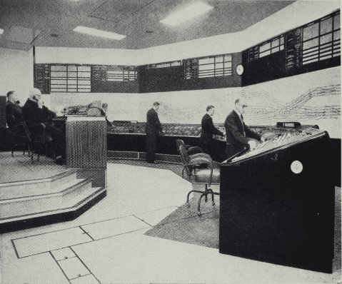
Control Room and Train Describer System
The control room in the signalbox has a route switch console, and above it an illuminated diagram, 53 ft. long and 4 ft. 6 in. high, arranged in four sections, with one signalman to each. Between the outer sections, set at an angle to the centre ones, are panels for train describer push buttons and signalman’s telephone switches. The train describer display indicators are above the diagram, on which the track circuit sections appear in distinctive colours. A red light at each end of one denotes an occupied section. The traffic controller has a desk on the central dais from which he can see the whole of the diagram, switch console and train describers.
There are 2,840 route lights. As soon as a route becomes cleared for a train, it is illuminated in white throughout the panel as so until the movement is completed and the route restored to normal. Flashing green lights serve as “train ready to start” indicators. They are extinguished when the relevant starting signal is cleared. The route switches, of plug-in design, are arranged in two groups, upper and lower, corresponding to the two directions of running through the area, and are coloured red for main and white for subsidiary signals and engraved each with its route identifying number. Alongside is a small plate describing the route.
For each signal there are switches covering the routes to which it leads. These lights are placed above the relevant switch groups. Individual point operation, when necessary, is effected by three-position switches, which must be placed in the central position before the points can respond to a route switch.
Turning a route switch energises the main signal lock relay reverse which, in turn, energises the associated subsidiary lock relays (where provided) reverse. The intervening subsidiary signal lock relays then reverse in sequence up to the next main signal. All signals are now ready to be cleared. The last subsidiary control relay then proves the track clear and points correctly set before the signal goes to clear. The intervening subsidiary control relays then operate, similarly in sequence, back to the main signal controlling entry to the section, the signals going to clear. All intervening control relays are now energised with full track circuit control throughout the route and all signals clear. In an emergency the signalman can put any intervening subsidiary to danger after the train has entered the section.
The describers give the description and destination of the train concerned, as set up in code by the originating signalman, and show what signal the train is approaching at the moment. The indication moves automatically as the train passes over the track circuits. Initially, the display at both the transmitting and receiving ends is shown as a flashing indication, with a buzzer sounding at the receiving station. The buzzer is silenced and both displays are steadied by the depression of an “acknowledge” key by the signalman at the box towards which the train is proceeding. Provision is made for manual operation in the event of any of the controlling signalling apparatus being out of order.
There is special provision for light engine movements between the Heaton Motive Power Depot and Manors Station bay platforms. The descriptions for these engines, on the appropriate signals being cleared, are transferred from the Newcastle receiver display to the transmitter display, and are sent forward automatically.
The train describer apparatus is of the all-relay telephone type, with relays on jack-in panels to facilitate routine maintenance. Open racking is used at the new signalbox, but at the outlying boxes relays are in dust-proof cubicles. The whole of the new signalbox is fully air conditioned and centrally heated; special care has been taken to provide a high degree of sound insulation in the control room.
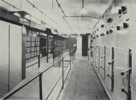
Relay Room and Electrical Equipment
The relay room, 85 ft. by 56 ft. by 18 ft., adjoins the control room, accommodating on two floors the interlocking, track, point indication, signal control, “stick” and other relays. There are approximately 850 lock relays, and 2,000 others for control, indications, releases, and so on. About 400 miles of single-core cable was used for their wiring. Multi-core cable connects the console with the track diagram. All wiring is in flameproof cable.
Traffic requirements necessitate a comprehensive telecommunications system, converging on the new signalbox. The staff there can make immediate contact with adjacent signalboxes, by separate direct telephone circuits. Communication also is provided with station and sidings staff at many points, and with signalmen as far as Durham, Blaydon, Tynemouth, and Killingworth, also with the controllers at Newcastle and Sunderland, who direct the traffic in the whole Newcastle District.
Automatic ringing out and selective calling in facilities on each circuit ease the burden of signalmen and regulator. There are 47 direct circuits to specific signals, enabling train crews to speak to the signalmen. Lamp indicators on the console show from which signal a call comes.
To minimise delays caused by frost, snow, or other kinds of bad weather, 29 “emergency point telephone plug points have been placed at selected important locations, connecting with the signalbox. Permanent way staff, by using portable plug-in handsets, can converse with the signalmen when testing the movement of points during snow clearing.
In addition similar plug-in points are placed in all lineside cable termination housings, connecting with a keyboard in the signal relay room. Maintenance staff outside can call those at the signalbox by using their portable telephones, and in turn be called by the production of a high frequency tone in loudspeakers alongside the track. At the important East and West junctions are others known as “talkback” loudspeakers, through which the signal relay room maintenance staff can converse with those maintaining the point motor and detection mechanisms and track circuit functions. This system can be extended to the signalbox control room in times of emergency for use by the traffic regulator.
In the centre of the telecommunications apparatus room is the main distribution frame on which are terminated all telecommunication cables entering and leaving the Central Station. These serve all telephones on the signalling system, the railway telephone exchange, and long-distance trunk circuits between London and Scotland. At this point the maintenance staff have complete control of all telephone cabling systems in the area, enabling alterations in routing and testing of faults to be carried out at a minute’s notice. A special fusing and cable termination system has been incorporated on the frame to protect staff and equipment from fault currents and surges occurring on the Newcastle electric traction system.
A complete system of controlled electric clocks, worked from a temperature-regulated pendulum master, covers the administrative offices and the new and adjacent signalboxes. Approximately 100,000 exposed contacts have to be maintained in a clean state, and to assist this humidity-controlled clean air is injected into the room and used air extracted.
There are more than fifty housings in which cables are terminated. Some are of steel, but brick has been used where a large number of cables converge. Cabling between the housings and the signalbox is multi-core, oil-impregnated, paper-insulated, lead-sheathed and armoured, and totals some 35 miles. Between housings and signals, point machines, and so on, rubber-insulated sheathed cable is used. Trackside cables are supported by hangers or run in ducts, and the main run of 45 cables is carried into the relay room on a steel gantry across four sets of freight lines. Inside the relay room, 85 multi-core cables are terminated on fused links, which protect from fault currents and surges occurring on the electrified lines, as the telecommunications circuits.
Power at 660 V. single phase is taken from two independent public supplies through oil-filled circuit breakers, and no standby alternator has been considered necessary. Ring main supplies to external signalling functions are connected through air-break circuit breakers, as are the 660/110 V. transformers feeding the signalbox 110 V. busbars. Thence supplies are taken to d.c. supply rectifiers, indication transformers, and 110 V. distribution system in the relay room. Automatic carbon dioxide fire protection is provided for the power cubicle, relay room, and so on.
The structural design of the control and relay rooms presented a number of problems. In the first stages of the erection sequence, the new framework had to be built round, and finally made to support, the existing arched station roof. The new signalling installation was brought into use on April 12.
This original article can be accessed in The Railway Magazine archive, along with all issues dating back to the 1800s! All you need to do is be a Railway Magazine subscriber: https://www.classicmagazines.co.uk/the-railway-magazine