An extract from the March 1957 issue of The Railway Magazine detailing the development and operation of conductor rail de-icing tenders. The text describes design features, testing, and functionality as reported at the time.
Development and Purpose
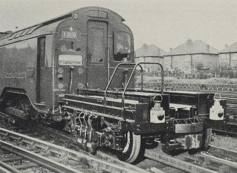
A further development by London Transport of precautions to prevent train delays in winter caused by conductor rail icing is the use of sleet tenders attached to the front and rear of an empty service train. One prototype tender has been completed at Acton Works, and another is under construction. These vehicles are to undergo tests on the western section of the Piccadilly Line. They will fulfil the function of the present sleet locomotives, of which the traction control equipment, now out-of-date, would be costly to modernise. Apart from the much lower initial and maintenance costs, the tender has a particular advantage over a locomotive in that no special crew is required.
Design and Equipment
The tender, which is of restricted height to afford an unimpaired view from the train driver’s cab, consists of a specially constructed four-wheel bogie, to which is fitted de-icing equipment similar to that of a sleet locomotive. There are three sets of crushing rollers, steel brushes and de-icing sprays. One of the three sets deals with the central negative rail, and the other two with the positive rail, according to which side of the track it is laid.
From the history of steam through to 21st century rail transport news, we have titles that cater for all rail enthusiasts. Covering diesels, modelling, steam and modern railways, check out our range of magazines and fantastic subscription offers.
Compressed air from the train system is used to lower the rollers and brushes, which are raised by spring pressure. The sprays are fed by an axle-driven pump from two interconnected 75-gal. tanks mounted on top of the bogie frame. Delivery is at the rate of 0.9 gal. of de-icing fluid per mile. The pump is cut out as required by disengaging a lever-operated dog clutch. To avoid damage to the pump in the event of all three sprays becoming blocked, a delivery pipe is fitted with a relief valve from which the fluid is returned to the tanks.
Operation and Safety Features
As the position of the positive rail varies from side to side of the track, a selector, in the form of a mechanically-operated cut-off valve, is provided on each side of the tender. This valve is operated by a lever carrying a small roller which drops below the positive rail. When the roller drops below a predetermined level (at the rail-end ramps) the spray on that side is cut off.
The tender is fitted with a spring-applied brake, which is normally released by air pressure. Thus, in the unlikely event of a breakaway, the brake would be applied automatically.
This article is available to subscribers of The Railway Magazine, along with every article from issues dating back to the 1800s! To subscribe, visit https://www.classicmagazines.co.uk/the-railway-magazine