A May 1969 report from The Railway Magazine details the wheel-loading and torsional-testing installation at the Railway Technical Centre, Derby. The system was designed to evaluate stress characteristics and torsional stiffness in rolling stock under controlled conditions.
Purpose of the installation
In certain types of rolling stock the suspension systems and torsional rigidity in the underframe can lead to riding irregularities under various loading, speed and track conditions. With new designs of longer, higher-load carrying stock and where construction is mainly centred on a fully welded integral base unit, it is desirable that reaction of the vehicles to various loading and torsional stiffness conditions is known in order to assess the requirements for high-speed operation.
A load-cell weighing installation in service at the Railway Technical Centre, Derby, built by Henry Pooley & Son Limited to detailed B.R. requirements, is providing facilities for evaluating torsional stiffness and load-distribution characteristics of new stock and also for assessing existing stock. It is the intention of B.R. to make a survey of all forms of rolling stock and to this end the weighing installation has been designed to accommodate virtually all wheelbases.
From the history of steam through to 21st century rail transport news, we have titles that cater for all rail enthusiasts. Covering diesels, modelling, steam and modern railways, check out our range of magazines and fantastic subscription offers.
Installation layout and operation
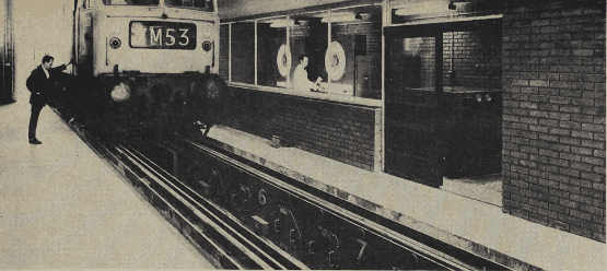
The installation is arranged with normal rail-approach facilities and consists of two crowbar-profiled rails placed centrally between guide rails and to each side of a foundation pit housing the hydraulic and electrical circuitry. Both rails are sub-divided into nine opposed load-cell weighing sections, each opposed pair having a capacity of 15 tons and being independently operated. The centre pair of weigh rails is equipped with hydraulically-powered jacks so that they can be separately raised and lowered to simulate all envisaged camber conditions.
Loads on both the central and the eight pairs of static weigh rails are transferred from the supporting load cells and a separately housed relay and control panel to two independent indicator consoles. Each of the dial indicators is equipped with twin pointers scanning a chart reading from 0 to 15 tons in divisions of 56 lb. One console is used to control and indicate loads on the eight pairs of static rails and the other houses controls for the automatic and manual operation of the centre rails.
Measurement and testing capability
Each pair of static rails is operated separately, selection being by means of a rotary switch on the indicator console. Gross weights are determined by positioning the rolling-stock wheels over any opposed pair of rails, setting the switch accordingly and noting the weight. The two pointers indicate left- and right-hand wheel loads, an arrangement which also shows the difference in loading on each wheel. In addition to the dial indicator, the console for the centre rails houses the hydraulic controls and incremental-height selector for both rails.
Twist testing is carried out with two opposing wheels stationed on the centre rails at two positions. To establish different loading conditions at differing angles, the centre rails are individually raised or lowered to provide varying degrees of tilt to a maximum of 1½ in. in either side of the level position.
Track conditions can be simulated on the Pooley machine to enable all aspects of wheel-loading and torsional rigidity to be evaluated. From a progressive pattern of testing, information is gained for improving riding properties. This will be used to evolve a standard acceptance requirement for all new vehicles.