An archive feature from June 1968 detailing strengthening work on Royal Albert Bridge, Saltash, including structural testing, engineering analysis, and modifications to accommodate increased axle loads.
INTRODUCTION
INTRODUCTION of 100-ton bogie tank wagons on specified routes of British Railways has led to the examination of structures on those where use of these wagons would affect economies in services and attract new traffic. With this in view, a thorough examination has recently been completed of the Royal Albert Bridge, carrying a single track which spans the River Tamar between St. Budeaux, Devon, and Saltash, Cornwall, on the Western Region lines.
In addition to an expansion of the freightliner network, the region is anxious to introduce high-capacity wagons for cement, iron ore and china clay. There is also a potential in the bulk movement of china-clay sand, large tips of which exist near the clay pits, which is suitable for building sand, and could be used by the construction industry in the London area.
From the history of steam through to 21st century rail transport news, we have titles that cater for all rail enthusiasts. Covering diesels, modelling, steam and modern railways, check out our range of magazines and fantastic subscription offers.
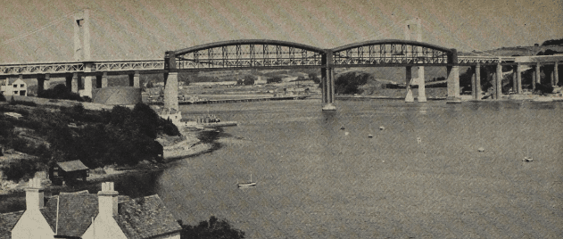
Photo: British Railways Western Region
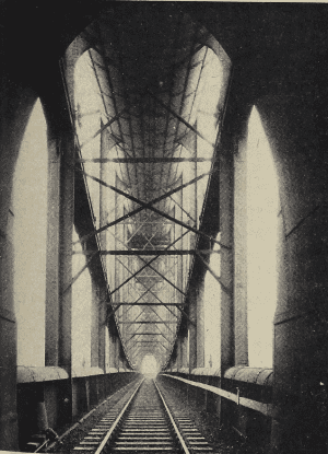
The bridge was built to the design of Isambard Kingdom Brunel, Engineer to the Cornwall Railway, and was opened by the Prince Consort on May 3, 1859. (An article celebrating its centenary appeared in the May, 1959, issue of The Railway Magazine.) Though the approach spans were renewed in 1928, the wrought-iron trusses of the two main 455-ft. spans are the originals. Each truss consists of a wrought-iron oval tube, forming an arch, and two suspension chains, one on each side of the tube, forming an invert to the arch and connecting the tube ends. At 11 points in the length of each truss the chains are connected to the tube by vertical standards, braced together by diagonal bars to resist the strains caused by unequal loading. The railway deck girders are suspended from the truss by the vertical standards, and from the chains at points between each standard. The trusses are 56 ft. deep at the centre, the tubes 16 ft. 9 in. broad by 12 ft. 3 in. high, and wrought ironwork in each 455-ft. span weighs 1,060 tons.
Technical study of the bridge was undertaken by British Railways Engineering Research Division at Derby at the request of the Chief Civil Engineer. The studies was made with the object of determining the stresses and fatigue life of the various parts of the structures, one of the more interesting requirements being to determine the fatigue hazard and its relation of the bridge if normal present-day traffic was augmented daily by four freight trains, comprising four heavy locomotives with 40 hopper wagons of 100 tons gross.
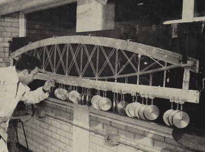
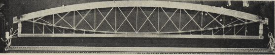
Photos: British Railways
Model testing and observations
Because of the structural complexity of the bridge, it was necessary to build up a model of one of the trusses and subject this to the heavier loading to ascertain the behaviour of the structure. Tests were also carried out on the bridge itself and the data obtained were used in making the model. It was found that when a train ran on to one end of the bridge, the chains stretched fractionally and caused a movement towards the loaded end of the chain joints. Because the girders did not move, a bending moment was set up in the verticals between the chains and the girder. This moment set up a fatigue condition, but by introducing a small diagonal tie, of 4 in. by 2 in. hollow steel section, between the point where the vertical member joined the track girder, and the suspension chain, bending is prevented, and fatigue from this source eliminated. Tests carried out by the Research Division established that, when 24 of these ties are installed on each truss, trains of 1,000 tons gross can be run over the bridge.
First bridge test was carried out in November, 1966, with two “D800” class 78.6-ton locomotives in tandem. Mechanical strain gauges were fixed to the bridge but, because of adverse weather conditions, results were obtained only from structural members below the chains; however, these gave enough information to enable the model. Second bridge test was made in April, 1967. In this, 20 “Walrus” 40-ton hopper wagons were sandwiched between “D1000” class 108-ton locomotives. Mechanical strain gauges were again used. This test, which was carried out with the train stationary, measured bending and shear conditions on all members above and below the suspension chains on the upstream side of the Devon span. The total train length exceeded that of a span, and the heaviest loading was 766 tons or 1.68 tons per ft.
During tests on the Devon span, eight of the members tested showed stress changes in excess of the calculated fatigue limit of 5.2 tons per sq. in., six of these members being below the suspension chains, on the fully instrumented section. This high stress level was caused by secondary bending of these members, induced by shearing action between the suspension chains and the track girder.
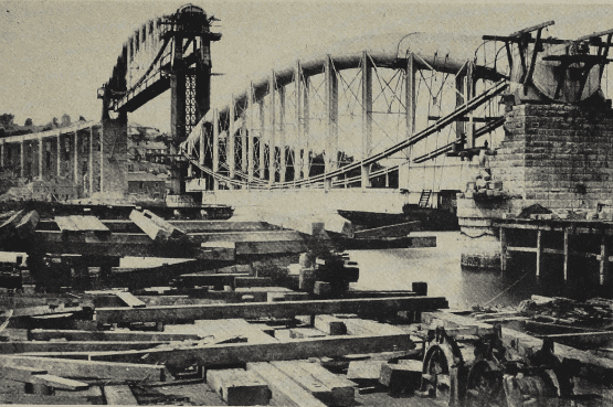
The bridge taking shape in 1858, the year before it was opened to traffic. One main span is in position and that on the Devon side is ready to be raised as the masonry pillars are built up
Further testing and strengthening work
Using test results obtained from the bridge, a perspex scale model, measuring 9 ft. 6 in., was made of one span, to simulate the behaviour of the wrought-iron bridge. So that the model would provide valid information on the behaviour of the bridge under proposed loads, it was necessary to build it to simulate behaviour under one type of load, and then use the model to predict the behaviour of the bridge under a second load, the results of which would then be used on the bridge to check the prediction.
These tests showed that the stresses caused by adverse effects affected by present-day traffic, an emphasis was changed to determining a modification which would bring the stresses within the fatigue limit. This modification was the fitting of diagonal ties, as mentioned, 24 to each span. These will be installed next year as part of an £80,000 improvement programme. Work started on this in 1967; all timber decking beneath the track, on the approach spans and on the main bridge, is being renewed and the wrought-iron suspension chains are having the old paint grit-blasted off and a special non-oxidising paint—Camerex N.O.P.—is being applied. This paint never dries hard, and will enable the metal underneath to expand and contract without the paint cracking. The downstream chains were painted last year, and those on the upstream side will be treated this year.
This article is available to subscribers of The Railway Magazine, along with every article from issues dating back to the 1800s! To subscribe, visit https://www.classicmagazines.co.uk/the-railway-magazine